
Write something

2d •
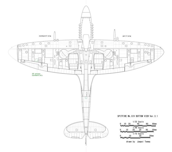
How did the Spitfire end up with an elliptical wing?
1934. You are staring at a seemingly impossible specification sheet from the British Air Ministry for a new interceptor. You need to achieve speeds of 350 miles per hour, requiring a paper-thin aerodynamic profile to minimize parasite drag. Simultaneously, you need a massive amount of lift for high-G dogfighting. Also, you cannot fit the armament in the engine cowling, meaning you must bury massive weapon systems, heavy breech mechanisms, and thousands of rounds of ammunition inside wings that are fundamentally supposed to be too thin to hold them. It is a brutal engineering paradox. Through first-principles, the obvious baseline solution is a straight-tapered wing with an aerodynamic twist. Mathematically, twisting the wing forces the air into an elliptical lift distribution, giving you an Oswald efficiency number near 1 to minimize induced drag during hard turns. However, this "obvious" solution fails spectacularly in reality. In a high-angle-of-attack dogfight, the narrow wingtips of a sharply tapered wing stall first, causing a fatal, unrecoverable snap roll. Worse, the physical chord of a tapered wing shrinks so rapidly that halfway down the span, the wing becomes physically too shallow to enclose the outboard machine guns unless you ruin your top speed by making the airfoil terribly fat. The breakthrough came when Supermarine's R.J. Mitchell and Beverley Shenstone realized that faking an elliptical lift distribution with a twisted wing was a flawed compromise, choosing instead to build a literal, mathematically pure elliptical wing. Natively, this shape achieved the perfect aerodynamic efficiency required to turn inside enemy fighters without bleeding airspeed, completely eliminating the need for drag-inducing twist. Crucially, it also solved the tip stall problem; the mathematically uniform wing meant the entire span approached the stall angle simultaneously, giving the pilot a violent warning shudder that allowed them to safely ride the absolute ragged edge of the flight envelope.
3
0
12d •
⚙️✈️Engines that Keep the World Flying: The CFM56 Powerhouses
From Airbus to Boeing, the CFM56 engine series has set an industry standard for powering single-aisle commercial aircraft. With unparalleled reliability and efficiency, these engines are the trusted choice for operators around the globe. Here’s a look at two of its legendary models: CFM56-5B: Powering the Airbus A320ceo Family The CFM56-5B reigns as the preferred engine for Airbus’s A320ceo lineup, chosen to power nearly 60% of these aircraft. It’s the only engine capable of powering every model of the A320ceo family with a single bill of materials, making it exceptionally versatile and cost-effective. Known for its simple and rugged design, the CFM56-5B delivers unmatched reliability, durability, and the lowest cost of ownership in its class. Over 30 years of service speaks volumes about its excellence and dependability. CFM56-7B: The Backbone of Boeing’s Next-Generation 737 Fleet For Boeing, the CFM56-7B is the exclusive powerplant for the Next-Generation 737 aircraft—a combination that has logged over 500 million flight hours and solidified itself as the most popular engine-aircraft pairing in commercial aviation. The -7B’s robust architecture ensures it’s as easy to maintain as it is to operate, offering the highest reliability, durability, and reparability at a low cost of ownership. With over 15,000 engines in service, this powerhouse is a symbol of rugged reliability. Together, these two engines exemplify the engineering excellence that drives modern aviation forward—keeping passengers safe, flights on schedule, and airlines competitive.
16d •
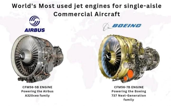
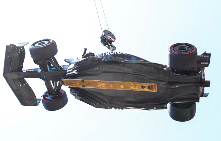
Formula 1 Downforces
Formula 1 represents a highly constrained optimization problem where the primary objective is minimizing lap time around complex trajectories. For aerodynamicists, the challenge is not just minimizing the aerodynamic drag for terminal velocity, but rather maximizing the aerodynamic efficiency, often expressed as the ratio of downforce generated to drag produced. Engineers must map out the car's aero map to ensure a stable aerodynamic platform across varying ride heights, yaw angles, and roll and pitch gradients. The overarching goal is to manipulate the flow field to maximize the negative lift coefficient, generating aerodynamic downforce that increases the normal load on the tires without adding inertial mass. As a vehicle's velocity exceeds 300 km/h, the dynamic pressure acting on the body of the chassis becomes immense; this pressure force is directly proportional to the density of the air and grows with the square of the car's speed. A standard automotive geometry inherently generates a positive lift vector due to the attached flow over its convex upper surfaces and the pressure recovery in its wake. This natural lift reduces the normal vertical load on the tire contact patch. The lateral grip a tire can produce is directly proportional to the vertical load pressing it into the ground; therefore, a reduction in normal load directly diminishes the tires' ability to generate lateral cornering forces and longitudinal braking forces. Furthermore, aerodynamic lift shifts the center of pressure relative to the center of gravity, inducing severe pitch and yaw instabilities that dynamically unload the axles and critically degrade the vehicle's transient handling response. The theoretical solution to this instability is to decouple the vehicle's normal load from its physical mass. By utilizing foundational aerodynamic relationships, where the total lifting or down-pushing force depends on the air's density, the square of the freestream velocity, the size of the aerodynamic surfaces, and the aerodynamic efficiency of the shape, engineers manipulate the bodywork to achieve highly negative lift. This generates a downward force vector that artificially increases the vertical load on the tires. Because this force scales exponentially with speed, it provides massive grip in high-speed corners without increasing the vehicle's physical mass. Keeping mass low is critical, as Newton's second law dictates that acceleration is inversely proportional to mass; any additional inertia would degrade the car's longitudinal acceleration and penalize its dynamic weight transfer during cornering.
2
0
24d •
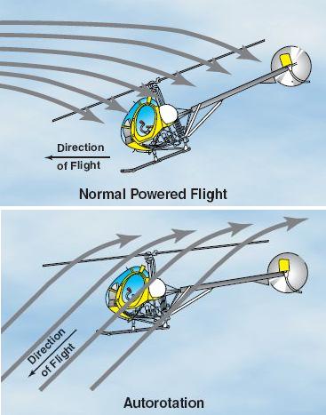
What is Autorotation?
Autorotation is a critical flight regime necessitated by the fundamental aerodynamic reliance of rotary-wing aircraft on engine-driven rotor velocity. Unlike fixed-wing aircraft, which rely on forward airspeed over static airfoils to maintain lift, helicopters depend entirely on the continuous rotational speed (Nr) of the main rotor system. In the event of a total powerplant failure, the primary source of thrust and lift is immediately compromised. Autorotation provides a controlled descent mechanism by converting the aircraft's potential energy (altitude) and kinetic energy (forward airspeed) into the rotational kinetic energy required to sustain Nr, ensuring continuous aerodynamic control and a survivable landing profile. The critical nature of this maneuver is amplified by the mechanical interconnectivity of the helicopter's drivetrain. If a powerplant seizes and remains coupled to the main transmission, the engine's internal friction and static mass will rapidly decelerate the rotor system. A catastrophic decay in Nr results in an unrecoverable loss of the aerodynamic lift vector and severe rotor stall. Furthermore, because the tail rotor is mechanically driven by the main transmission to counteract main rotor torque, a rapid loss of main rotor drive also compromises directional yaw control. Therefore, immediately decoupling the failed powerplant and transitioning to an autorotative state is paramount to maintaining structural stability and aircraft control. Physically, autorotation is achieved by manipulating the aerodynamic vectors acting on the rotor blades. During powered flight, air is drawn downward through the rotor disk (induced flow). In an autorotation, the relative wind reverses, flowing upward through the rotor disk as the aircraft descends. By lowering the collective pitch, the pilot reduces the blade's angle of attack (AoA) to mitigate drag and prevent aerodynamic stall. This upward relative wind alters the resultant aerodynamic force vector, dividing the rotor disk into three distinct aerodynamic regions: the driven region (near the tip, where drag exceeds thrust), the driving region (mid-span, where the total aerodynamic force vector is inclined forward of the axis of rotation, generating autorotative thrust), and the stall region (near the root). The forward acceleration produced in the driving region precisely balances the aerodynamic drag of the driven region, achieving a steady-state autorotative Nr.
2
0
29d •
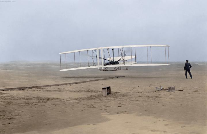
How did the Wright Flyer take off and land?
In the early 20th century, the race to achieve the first powered, controlled, and sustained heavier-than-air flight was defined by extreme engineering constraints, primarily the relationship between weight and thrust. When Orville and Wilbur Wright were designing the 1903 Wright Flyer, they were acutely aware that their bespoke, 12-horsepower cast-aluminum engine provided barely enough thrust to keep the 600-pound aircraft aloft. Their overarching goal was not necessarily to build a practical, everyday vehicle, but simply to prove that sustained powered flight was aerodynamically possible. Consequently, every single component of the aircraft was scrutinized for weight reduction and aerodynamic efficiency, meaning luxuries like complex suspension or heavy rolling chassis systems were entirely out of the question. Despite their intense focus on the aerodynamics of flight, the physical reality of getting into the sky and returning safely to the earth presented a massive hurdle. To take off, an aircraft must reach its minimum rotational speed, but rolling wheels across the soft, uneven sand of Kitty Hawk, North Carolina, would generate immense ground friction. The brothers' low-powered engine simply could not overcome this rolling resistance to achieve takeoff speed. Furthermore, the aircraft needed a way to touch back down without shattering its fragile spruce and ash framework. The challenge was dual-natured: find a way to accelerate smoothly on the ground with almost no rolling resistance, and design a lightweight structure that could absorb the moderate shock of a controlled landing. To solve this, the Wright brothers completely abandoned the concept of integrated wheels, reasoning that carrying heavy wheels into the air just to use them for a few seconds on the ground was a gross waste of their limited thrust. Drawing from their earlier glider experiments, they knew that simple wooden skids were sufficient for sliding to a halt in the sand upon landing. For the takeoff problem, they engineered an external, decoupled solution: a 60-foot wooden launching track. By separating the takeoff running gear from the aircraft itself, they effectively reduced the aircraft's airborne weight while bypassing the high friction of the sandy beach, allowing the engine's thrust to be dedicated entirely to acceleration and lift.
0
0
1-18 of 18
powered by
skool.com/valueknow-9324
✈️ Want to learn about aerospace with aerospace engineers? 70k+ students worldwide have taken our courses. Join now and access our courses for free.
Suggested communities
Powered by