Activity
Mon
Wed
Fri
Sun
Jun
Jul
Aug
Sep
Oct
Nov
Dec
Jan
Feb
Mar
Apr
May
What is this?
Less
More
Owned by Lluís
✈️ A community for engineers who are serious about aerospace. Technical depth, real careers and the right people.
Memberships
AV8R SCHOOL on Skool
332 members • Free
26 contributions to Break Into Aerospace

10h •
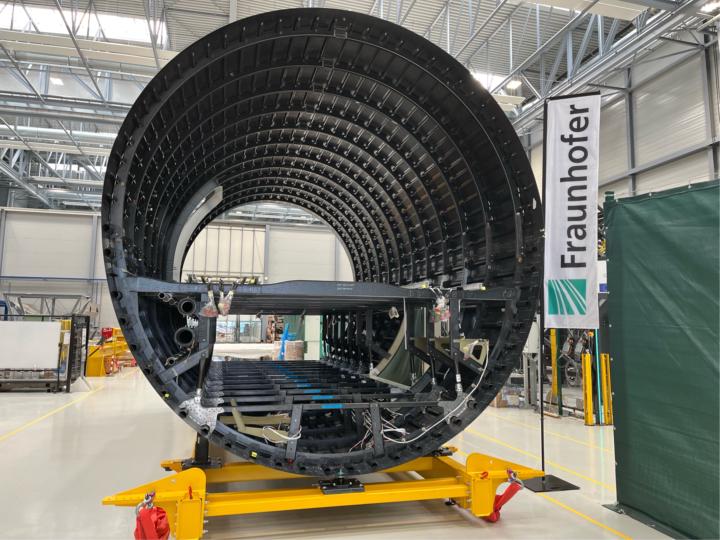
Understanding the Aircraft Fuselage
The fuselage is the main body of an aircraft, but from a structural engineering perspective, it is a complex assembly designed to maintain aerodynamic shape, protect internal contents, and most importantly bear significant flight and pressure loads. 1. The Core Functions What does the fuselage actually do? - Load Bearing: It must withstand forces from maneuvers, take-off, landing, and internal pressurization. - Shape Definition: It provides the aerodynamic profile necessary for flight. - Environmental Protection: It protects passengers and equipment from external conditions. 2. Structural Classifications In aerospace, we categorize structures based on how critical they are: - Primary Structure: Critical load-bearing elements.If these fail, the entire aircraft is at risk (e.g., the main fuselage shell). - Secondary Structure: Elements that only carry local aerodynamic or inertial loads (e.g., fairings or the dorsal fin). 3. The "Stiffened Shell" Concept Modern pressurized aircraft are essentially thin-walled pressure vessels. Because a simple thin skin would buckle under compression, we use a "stiffened shell" concept. The key components working together are: - Fuselage Skin: Carries the primary cabin pressure loads and shear. - Stringers (Longitudinals): Longitudinal members that stiffen the skin and carry axial loads (tension/compression). - Frames (Transversals): Circular or oval members that maintain the fuselage's cross-sectional shape and prevent the stringers from buckling. - Bulkheads: Heavy-duty frames located at ends of pressurized sections or where major loads (like wings) are attached. - Longerons: Longerons are heavy longitudinal stiffeners designed to carry particularly large loads, acting as primary structural members within an airframe. While similar to stringers in their longitudinal orientation, they are distinguished by their greater cross-sectional area and the intensity of the loads they are engineered to handle.

1 like • 7h
Semi-monocoque structures are the most common for aircraft, particularly commercial aircraft. There are some exceptions though, such as the Deperdussin Monocoque. Indeed maintenance is a big issue to consider when designing structures
3d •
We just hit 100 members. Now everything changes.
100 members in a few months. Zero paid ads. Zero paid promotion. Pure organic growth and word of mouth. I did not expect that. And it told me something important: there is a real gap for an aerospace engineering community. I read every single one of your profiles. From pilots to mechanical engineers blocked by "no aerospace experience". Maintenance professionals who touch aircraft every day but can't cross into design or other aerospace fundamentals. Software developers, electrical engineers, people from completely unrelated fields, all trying to get into the same industry. Pilots looking to learn in depth about the engineering of the aircraft they are flying. That's why the name changes today. We are rebranding to Break Into Aerospace. Here is what is unlocked today: - 15 aerospace engineering courses. Aviation to space. With shareable certificates. You can now access all of them. - 25+ Aerospace Company application guides, with 20+ actions to take to get hired at companies like SpaceX, Airbus, etc. - Live Q&As starting soon. - A professional network of engineers at every level of the industry. Hiring guides for mechanical, electrical and software engineers crossing into aerospace coming within days. For maintenance technicians and pilots, I'm building something special for you too. The community is free for everyone already here. In 48h the community goes to paid for new members. $19/month or $149/year, Founding Member rate. Last free passes close this weekend. If you know a colleague, friend, or someone who may be interested in joining for free, they have 48h. You showed up when this was just an idea with a generic name and almost no content. That deserves more than a discount code. I truly appreciate it. And we are launching something new: Aerospace Careers Q&A. Every week one member of this community will share their story. How they got into aerospace, or how they plan to. What their goal is. What is standing in the way. The community responds, advises, and connects. Your story might be exactly what someone else needs to hear. If you want to be the first, comment below or send me a message. I will reach out personally to the first five who put their hand up.
5
0
5d •
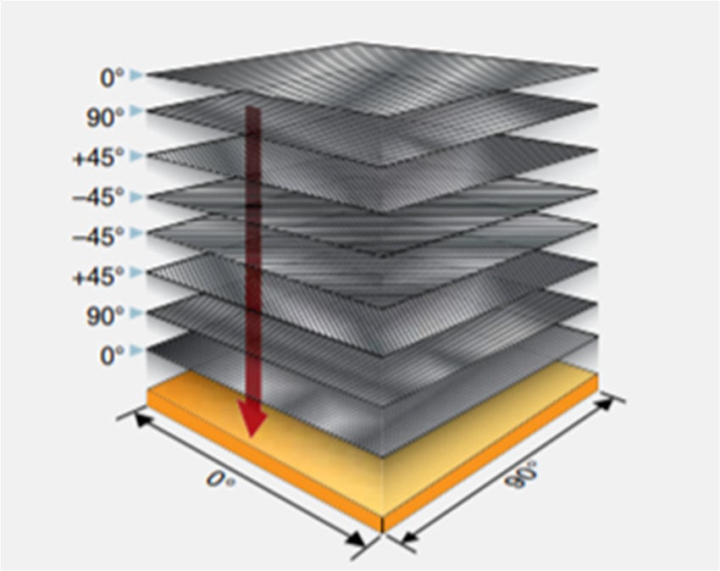
Today, let’s extend our understanding of material behavior in Aerospace Structure & Materials (ASM) by looking at two important classifications: quasi-isotropic and orthotropic materials.
Quasi-isotropic materials are engineered (mainly in composite laminates) to behave almost like isotropic materials in-plane. By arranging fiber orientations (e.g., 0°, ±45°, 90°), the laminate achieves nearly uniform properties in multiple directions. This approach is widely used when designers want the predictability of isotropic materials with the lightweight advantage of composites. Orthotropic materials, on the other hand, have three mutually perpendicular directions with different material properties. That means strength and stiffness vary along each principal axis. Many aerospace composites—and even some natural materials like wood—are orthotropic. This allows engineers to precisely tailor structural performance based on load paths. In practice: - Quasi-isotropic → balanced, uniform behavior (simplified design) - Orthotropic → directional optimization (high efficiency, high performance) Understanding these distinctions is crucial for designing advanced aerospace structures where load direction, weight reduction, and structural efficiency must be carefully balanced.
1 like • 4d
It's key to understand the requirements each aerospace component may have. Start with the requirements and deduce the right material and properties. Nice work!
5d •
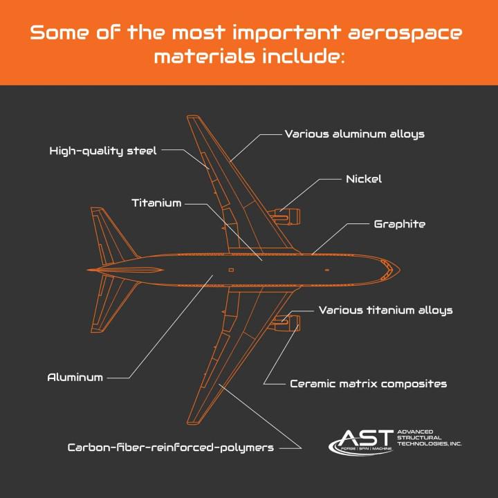
In Aerospace Structure & Materials (ASM), material selection is one of the most critical decisions in aircraft design.
The four primary categories of materials used in aerospace structures are: - Metals & Metal Alloys - Composites - Ceramics - Polymers Early aircraft were built from wood and fabric, but modern aviation has evolved significantly. Today, materials like aluminum, titanium, steel, and advanced composites dominate the industry, making up around 80–90% of a typical airframe’s structural components. Each material class plays a distinct role: - Metals → high strength, ductility, and well-understood behavior - Composites → exceptional strength-to-weight ratio and tailored properties - Ceramics → high-temperature resistance (ideal for extreme environments) - Polymers → lightweight and versatile for non-structural and semi-structural applications The real challenge in ASM is not just knowing these materials—but selecting and combining them efficiently to achieve strength, weight reduction, durability, and performance optimization.
1 like • 5d
Nice insight Mahin. Also, 3D printed materials are already present in aerospace, from strong durable plastics to 3D printed metals. Materials science in aerospace is moving fast currently. Thanks for the post!!
6d •
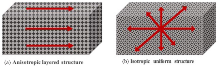
In Aerospace Structure & Materials (ASM), two fundamental concepts are isotropic and anisotropic materials.
a) An anisotropic material behaves differently depending on the direction of the applied load. Composite materials such as CFRP (Carbon Fiber Reinforced Polymer) are highly anisotropic because fiber orientation controls stiffness and strength. This directional behavior is what makes composites both powerful and challenging in aircraft design. b) An isotropic material has the same mechanical properties in every direction. Its strength, stiffness, and behavior remain uniform regardless of loading orientation. Metals like aluminum are commonly treated as isotropic materials in aerospace design because they simplify analysis and provide predictable structural performance. Modern aerospace engineering combines both concepts: - Anisotropic materials → lightweight, high strength-to-weight optimization - Isotropic materials → simplicity, reliability, uniform behavior The real engineering challenge is understanding when to use each material system for maximum structural efficiency.
1 like • 6d
Thanks for your contributions Shadat! Indeed, anistropic and isotropic materials are a key distinction in aerospace and other engineering domains where a structure must resist a specific stress. For instance, fuselages will mostly have isotropic materials (or a combination of CFRP fibers in 0, 45º, 90º etc angles) to avoid irregular deformations since the stress comes primarily due to the interior vs. exterior pressure, but specific surfaces like wing components could benefit from being anisotropic due to their primary bending loads they have to carry.
1-10 of 26

@lluis-foreman-8720
Lluís Foreman, Aerospace Engineer MSc
Active 10m ago
Joined Nov 29, 2025