Write something
I teach because I enjoy helping teams work faster and make fewer mistakes.
I teach because I enjoy helping teams work faster and make fewer mistakes. At most companies I become the go-to person for AutoCAD and, in the last two decades, AutoCAD Electrical. Plus, my coworkers keep bugging me to do it. Background I started on a drafting board in the late 1980s, moved to AutoCAD on MS-DOS 5.1, and have worked through every major CAD and Windows release since 1990. Consulting has given me a wide view—45 companies across 27 cities in 7 states, more than 500 projects, and 300+ end customers. I’m still learning; I picked up a new command last week because a customer relies on it. Selected organizations supported U.S. (Air Force, Army, Navy); Rolls-Royce Energy; Cooper Industries; Parker Hannifin; Tecumseh Products; Saturn; Ford; and public agencies including the States of Indiana and Ohio and Michigan and the Cities of Indianapolis, Toledo, Columbus, and Detroit. Project domains Steel and glass furnaces; oil & gas pump stations; wastewater treatment facilities; schools, colleges, and universities; hospitals; federal and state correctional facilities; and manufacturing systems for components used in the Space Shuttle era. What you can expect Straightforward standards, repeatable workflows, and clear documentation tuned for electrical engineers and designers—so your teams and panel shops move quickly with fewer revisions. I’m here to share what works and tailor it to your environment.
New Item in the Classroom Section
Hey everyone, quick update: I added a new item to the Classroom section. If you run into any issues, ask here or DM me. I’m still new to Skool, so thanks for your patience. I plan to post other videos soon. I am happy to record a demo run-through if that helps. Feedback welcome, and I hope this is useful!
AutoCAD Electrical Quik Reference Guide
Here’s a quick AutoCAD Electrical reference guide that I usually print for people. It’s designed to be pinned up on a wall or kept in a desk drawer so it’s easy to glance at whenever needed.
AutoCAD Electrical Manual 2010
Here’s a PDF copy of one of the original AutoCAD Electrical manual—very similar to the printed versions that came with the CD/DVD packages back in the late 2000s. While it’s dated (from 2010), not much has actually changed in the software since then, aside from the added option to use an SQL database. This manual is still an excellent resource for beginners: it’s well-organized, less cluttered than the current online documentation on Autodesk’s site, and easy to navigate. I especially like that it can be used for training or quick reference when working onsite or in remote areas without internet access. I just wanted to share this early on as I continue putting together more training material.
2
0
Example of a Common Question
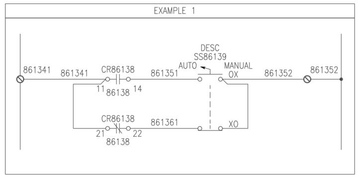
Here’s a perfect example of an issue that came up today: Someone was editing a drawing they had been given, and the wires were simply drawn running into each other—without a node (dot) to show a connection. In another place, the drawing used an angled tee connection symbol instead. This confused them because they have never seen angle tees. Below is how I explained it to them, and I thought it would be helpful to share here as well. Understanding Nodes and Wire Junctions in Schematics In schematic diagrams, a circular dot at the intersection of two or more wires is called a node or junction. It explicitly indicates an electrical connection. Sometimes, you’ll also see an angled tee section symbol. This is another way to represent a wire junction, and it is often used when the wiring sequence is important. The orientation of this symbol tells the electrician or panel builder the exact order in which wires should be connected. I’ve attached three example snapshots. All three are valid, but each communicates your wiring intent a little differently. --- Example 1 – Clear, Step-by-Step Guidance This method is very direct and leaves little room for misinterpretation. * Wire from terminal 861341 to pin 11 on relay CR86138. * Add a second wire (or preferably a jumper, when allowed) from pin 11 to pin 21. * On the right side, do the same—jumper between the two contacts on the selector switch. * Finally, run a single wire from the switch to terminal 861352. This approach clearly communicates your intent and avoids confusion. --- Example 2 – Traditional, But Risky (In My Humble Opinion) This is the most common traditional style and can be drawn slightly faster, but it leaves too much interpretation up to the panel builder. * The intent is still to wire from terminal 861381 to pin 11 of relay CR86139 , then jumper to pin 21. * However, because the jumper isn’t explicitly shown, a less experienced builder might interpret this as two separate wires from the terminal —one to pin 11, and another to pin 21.
0
0

1-6 of 6
powered by

skool.com/autocad-electrical-7513
All things AutoCAD Electrical training, Q&A, how to think outside the Building outside the Box. I am here to help with your toughest Acad-E problems.
Suggested communities
Powered by
