Activity
Mon
Wed
Fri
Sun
Aug
Sep
Oct
Nov
Dec
Jan
Feb
Mar
Apr
May
Jun
What is this?
Less
More
Memberships
AutoCAD Electrical
125 members • Free
Fulltime Freedom
6.3k members • Free
Software Developer Academy
26.4k members • Free
4 contributions to AutoCAD Electrical

18d •
My Story
Hi guys I did drawing back in the days, electrical drafting. It was funny, I miss it a lot, a lot pressure but fun! I loved drawing on autocad!

1 like • 15d
Agreed. It is fun! What kind of designs did you do?
1 like • 14d
@Charlton Somiah , nice! What part of that process excited you the most?

19d •
June 13th and 14th, I am officially starting
Hi everyone, First and foremost, I want to sincerely apologize for the delay. I promised to have our training videos starting back in January, and I am deeply sorry for letting you down. To be completely transparent with you, the last few months have been incredibly challenging. I lost my job right around the Christmas holidays and spent January transitioning into a new company. Shortly after that, I faced a major health scare, a borderline stroke. Going through that health scare gave me a massive wake-up call and a renewed sense of urgency. It made me realize how important it is to get all of this specialized knowledge out of my head and share it with the next generation. What you are getting in this program isn't just my own experience; it is the culmination of 30 years of wisdom passed down to me by hundreds of brilliant mentors. Combine that with my unique, fast-paced brain, fueled by a mix of ADHD/OCD and an absolute obsession with workflow efficiency, and you get a very practical, highly optimized way of designing. This weekend, June 13th and 14th, I am officially starting. I am launching a "Starter Program" with short, punchy, and foundational videos. They are designed specifically for absolute beginners who have never opened AutoCAD Electrical before. My goal is for you to learn something new and valuable with every single video. To help me tailor this exactly to what you need, please drop any specific questions you have in the comments. I will create targeted video responses to answer them. Lastly, please be a bit gracious with me on the production value! I am definitely not a video or sound editing master yet, but I promise to get better and more polished the more videos I do. Thank you so much for your patience, your understanding, and for sticking with me. Let's build something great together.
0 likes • 15d
@Deekshith Vaggu, here would probably be the easiest honestly
0 likes • 15d
What version of ACE will you be focusing on? I know some companies (the one I work for) does not like to be the first on new things and still runs on 2023
Sep '25 •
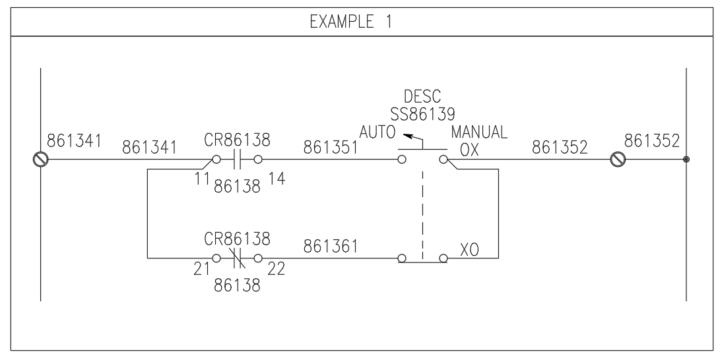
Example of a Common Question
Here’s a perfect example of an issue that came up today: Someone was editing a drawing they had been given, and the wires were simply drawn running into each other—without a node (dot) to show a connection. In another place, the drawing used an angled tee connection symbol instead. This confused them because they have never seen angle tees. Below is how I explained it to them, and I thought it would be helpful to share here as well. Understanding Nodes and Wire Junctions in Schematics In schematic diagrams, a circular dot at the intersection of two or more wires is called a node or junction. It explicitly indicates an electrical connection. Sometimes, you’ll also see an angled tee section symbol. This is another way to represent a wire junction, and it is often used when the wiring sequence is important. The orientation of this symbol tells the electrician or panel builder the exact order in which wires should be connected. I’ve attached three example snapshots. All three are valid, but each communicates your wiring intent a little differently. --- Example 1 – Clear, Step-by-Step Guidance This method is very direct and leaves little room for misinterpretation. * Wire from terminal 861341 to pin 11 on relay CR86138. * Add a second wire (or preferably a jumper, when allowed) from pin 11 to pin 21. * On the right side, do the same—jumper between the two contacts on the selector switch. * Finally, run a single wire from the switch to terminal 861352. This approach clearly communicates your intent and avoids confusion. --- Example 2 – Traditional, But Risky (In My Humble Opinion) This is the most common traditional style and can be drawn slightly faster, but it leaves too much interpretation up to the panel builder. * The intent is still to wire from terminal 861381 to pin 11 of relay CR86139 , then jumper to pin 21. * However, because the jumper isn’t explicitly shown, a less experienced builder might interpret this as two separate wires from the terminal —one to pin 11, and another to pin 21.
0 likes • May 8
Yeah, can’t say that I have ever used angled T’s before. Yet.
Apr 24 •
What do you struggle with?
I struggle with designing my inside panel layout in a way that keeps our panel shop guys from hunting me down and asking me, "What in the world were you thinking?" One of them is currently building what is essentially an R&D panel. Fun times. What do you struggle with?
0
0
1-4 of 4

Active 3d ago
Joined Apr 19, 2026
Greater Chattanooga, TN